




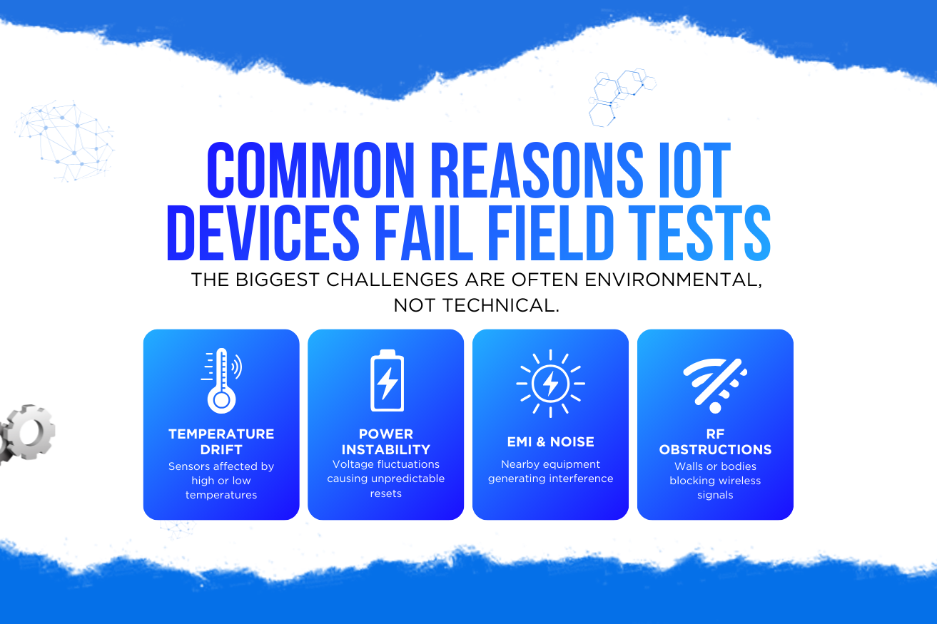
A device that passed every test on the bench starts behaving strangely three months after installation. Readings drift. Units reboot at night. One site reports constant faults while an identical site reports none. Nothing in the code changed.
This is the most common and most expensive pattern in connected products, and it has a consistent explanation: laboratory conditions remove the variables that actually break hardware. Stable temperature, clean power, low interference, short cable runs, careful handling — every one of those disappears the moment a device is installed somewhere real.
This article covers the physical failure modes that manufacturers most often overlook, how each one presents in the field, and the design decisions that prevent them while they are still cheap to make.
Why the Bench Lies
Bench testing is designed to answer whether a device functions. Field reliability depends on whether it keeps functioning across every combination of conditions it will meet over years. These are different questions, and passing the first tells you very little about the second.
| Condition | On the bench | In the field |
|---|---|---|
| Temperature | Stable room temperature | −20°C to +60°C, cycling daily |
| Power | Clean lab supply | Sag, spikes, brownouts, shared with motors |
| RF environment | Quiet | Wi-Fi, drives, welders, other radios |
| Mechanical | Sitting on a desk | Vibration, shock, torque on connectors |
| Humidity | Controlled | Condensation cycles, wash-down, dust |
| Installation | By the designer | By a technician on their eleventh job today |
| Duration | Hours or days | Three to ten years, continuously |
The last row deserves particular attention. Most field failures are not instantaneous — they are the accumulated result of thousands of cycles of stress that no short test can reproduce.
Hardware rarely fails because it was designed badly. It fails because it was validated against conditions that were kinder than reality.
Seven Reasons IoT Devices Fail After Deployment
Temperature drift — the silent sensor killer
Every analogue component has a temperature coefficient. Voltage references shift, oscillators change frequency, ADC offsets move, and battery capacity falls sharply in the cold.
The danger is that the device keeps reporting confidently. There is no error, no alarm — just numbers that are slightly and increasingly wrong. Systems built on those readings make quietly worse decisions over time, and nobody suspects the sensor.
- Characterise across the full operating range, not just at ambient
- Use a temperature-compensated reference where accuracy matters
- Measure board temperature and apply correction in firmware
- Report the compensation state so drift is visible rather than hidden
Power noise and voltage instability
Field power is rarely clean. Motors starting on the same circuit cause sags. Inductive loads produce spikes. Long supply runs drop voltage under load. Solar and battery installations vary continuously.
The classic symptom is a device that reboots without any pattern the logs can explain, often correlating with a machine cycle nobody thought to record. Brownouts are especially destructive because a supply that dips without fully collapsing can leave a microcontroller in an undefined state or corrupt a flash write in progress.
- Specify input range and transient tolerance for the worst site, not the typical one
- Fit proper input protection: TVS, bulk capacitance, and a reverse-polarity path
- Use brown-out detection with a defined, safe reset behaviour
- Make flash writes atomic so a mid-write power loss cannot corrupt configuration
- Log reset cause — it is often the only evidence you will get
Electromagnetic interference from nearby equipment
Industrial sites are electrically hostile. Variable-frequency drives, welders, contactors, and switching supplies inject noise into signal lines, power rails, and ground.
Symptoms include intermittent sensor spikes, corrupted serial communication, and radio links that work until a specific machine starts. Because it is correlated with production activity rather than time, EMI is often misdiagnosed as a software bug for months.
- Design grounding and return paths deliberately; avoid shared high-current returns
- Filter at every enclosure entry point
- Use differential signalling for cable runs of any length
- Add CRCs and sanity limits so corrupted data is rejected rather than trusted
- Test alongside the actual equipment on site, not in a quiet lab
Moisture, condensation, and ingress
Sealing is usually treated as an enclosure rating rather than a system behaviour, which is why so many IP-rated products still fail. A sealed box that warms during the day and cools at night pumps air — and therefore humid air — past marginal seals with every cycle.
The result is internal condensation, corroded contacts, and leakage paths that shift analogue readings before anything fails outright.
- Rate for immersion where wash-down or pooling is plausible, not just splash
- Use a breathable vent to equalise pressure without admitting liquid
- Conformal coat boards exposed to humidity or chemicals
- Choose connectors rated for the environment; they usually fail before the enclosure
Mechanical stress and connector fatigue
Vibration works fasteners loose, fatigues solder joints on heavy components, and abrades cables against edges. Connectors take side loads they were never rated for because a cable was routed at an awkward angle during installation.
Intermittent connections are among the hardest faults to diagnose remotely, because the device works perfectly whenever an engineer is standing next to it.
- Provide strain relief and specify cable routing in the installation guide
- Mechanically support heavy components rather than relying on solder
- Use locking connectors in any vibrating environment
- Test at the real vibration profile and duration, not a token shake
Installation variance
The device may be perfect and still produce useless data because of where it ended up. A temperature probe near a door, a vibration sensor on a guard rather than a bearing housing, an antenna against a metal panel — each produces plausible readings that describe the wrong thing.
This failure is invisible in every dashboard, because the data looks entirely normal. It is only detectable by comparing an asset against its peers, or by verifying installation at commissioning.
- Design mounting so the correct orientation is the easy one
- Include a commissioning self-check that validates signal plausibility on site
- Capture installation photographs as part of the process
- Cross-check each asset against similar assets to flag outliers automatically
Ageing and end-of-life effects
Some failures are simply time. Electrolytic capacitors dry out, especially when run warm. Flash memory wears out under frequent writes. Batteries lose capacity, and their internal resistance rises so the device browns out during a transmission burst long before the stated capacity is used.
These failures cluster, which makes them commercially dangerous: a whole production batch can begin failing within the same few months, years after shipping.
- Derate components thermally; a cooler part lasts disproportionately longer
- Minimise flash write frequency and use wear levelling
- Validate the battery under load at low temperature, not just at nominal capacity
- Report battery voltage under load so degradation is visible before it is terminal
Matching Field Symptoms to Physical Causes
Remote diagnosis is mostly pattern matching. The shape of a failure over time usually identifies its cause faster than any log will.
| Observed pattern | Most likely cause |
|---|---|
| Fails at night or early morning | Temperature minimum, or condensation |
| Fails during production hours only | EMI or power disturbance from machinery |
| Accuracy degrades slowly over months | Sensor drift, ageing, or fouling |
| Reboots with no pattern in logs | Brownout or a watchdog firing on a stall |
| One site fails, identical sites do not | Installation variance or local power quality |
| Reading is stable but implausible | Wrong mounting location or failed sensor reporting a default |
| A whole batch fails within weeks of each other | Component ageing or a supplier change |
| Works whenever an engineer visits | Intermittent connection disturbed by handling |
Capturing the data needed to use this table is a design decision. Reset cause, board temperature, supply voltage under load, and error counters cost almost nothing to report and turn an unexplained fault into a diagnosis.
Designing for the Field From the Start
These practices are also what make the transition from a small trial to a full rollout survivable — the failure pattern that causes so many programmes to stall after the pilot phase.
Frequently Asked Questions
Conclusion
IoT devices fail in the field for reasons that are physical, cumulative, and almost entirely predictable. Temperature moves analogue behaviour. Power is dirty. Machinery radiates. Enclosures breathe. Vibration loosens things. Installers are not designers. Components age.
None of this is unsolvable, but none of it is discoverable on a bench either. Write the environmental specification first, make devices report enough about themselves to be diagnosed remotely, fail loudly rather than plausibly, and put an early batch in the worst place you can find. That is the difference between a product that survives its warranty and one that quietly stops being trusted.